

Tolerance Control for CNC-Machined Robot Joint and Gripper Parts
Robot joints and grippersfail in the field more often because of accumulated tolerance stack-up thanbecause of a single out-of-spec part. When you are sourcing CNC-machinedcomponents for a robotic arm, the question is rarely “can this shop hit ±0.01 mm?”Most competent job shops can, on a single feature, under controlled conditions.The real question is which features actually need that tolerance, and whetherthe shop's process can hold it consistently across a full production batchwithout driving up cost and lead time on features that don't need it.
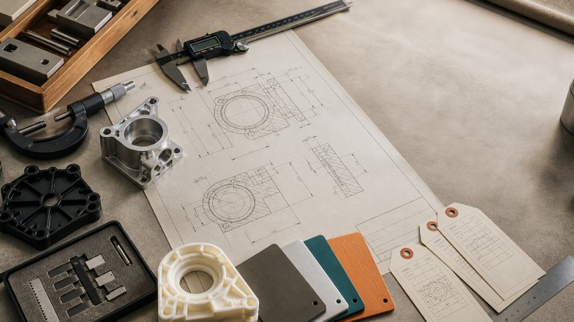
Where toleranceactually matters in a robot joint
A typical robot jointassembly — housing, bearing seat, flange, output shaft — has maybe 15–20dimensioned features. In our experience reviewing customer drawings, only 3–5of those features are truly tolerance-critical. The rest can run on generaltolerances (ISO 2768-m or -f) without affecting function.
• Bearing bores and shaft fits — directly control preload andradial play. Even 0.02 mm of oversize on a bearing bore can introducemeasurable backlash in the joint.
• Mounting flange hole positions — errors here don't staylocal; they stack up across every joint in the kinematic chain, showing up asend-effector position error many times larger than the individual tolerance.
• Gripper jaw contact faces — flatness and parallelism mattermore than the linear dimension. A jaw face that is dimensionally correct butnot flat will grip inconsistently and generate part-to-part variation inclamping force.
• Sensor mounting bosses — encoders and torque sensors areoften more sensitive to angular tolerance than linear tolerance; a 0.1° errorat the boss can translate into a meaningful reading offset.
A referencetable: where to hold tight tolerance, and where not to
The table below reflectsthe tolerance classes we actually see requested — and actually machine — onrobot joint and gripper drawings. Use it as a starting point for a DFMconversation with your supplier, not as a substitute for your own engineeringjudgment.
Feature | Standard practice | Achievable at CUSTPARTS | Typical risk if ignored |
Bore for bearing seat | H7 (+0.000/+0.025 for Ø30) | ±0.01 mm on critical bores | Bearing preload loss, play in joint |
Flange mounting holes | ±0.05 mm position | ±0.02–0.03 mm position | Misalignment stacking across joint chain |
Gripper jaw contact face | Flatness 0.02 mm / 100 mm | Flatness 0.01 mm / 100 mm | Uneven clamping force, part slip |
Non-critical housing walls | ±0.1 mm (general tolerance) | ±0.1 mm (cost-optimized) | Over-tolerancing inflates cost/lead time |
Why holding±0.01 mm on every dimension backfires
It is tempting to specify±0.01 mm across the whole drawing “to be safe.” In practice this does theopposite of what you want:
• Cycle time increases because every feature now needs afinishing pass, in-process measurement, and often a second setup — evenfeatures with no functional reason to be tight.
• Machine and fixture thermal drift becomes a real factor onceyou're chasing ±0.01 mm on multiple non-critical features in the same part,which increases scrap rate rather than reducing it.
• Cost and lead time both go up, and the quoted price stopsbeing comparable to what a well-toleranced drawing from a competitor would cost— which is one of the most common reasons a technically sound part getsre-quoted elsewhere.
A drawing with 3–5features called out at ±0.01–±0.02 mm and the rest at general tolerance is bothcheaper to produce and, counter-intuitively, more consistent in the featuresthat matter, because the machine and the operator's attention are concentratedwhere they have the most impact.
What to checkbefore you commit to a supplier
Tight tolerance on papermeans nothing if it isn't verified on the part. Before releasing a productionorder, ask your supplier for:
• A first-article CMM inspection report against your drawing,not just a certificate of conformance.
• Confirmation of which machine and fixturing will be used forthe critical bores — 3-axis vs. 5-axis setup changes how many operations (andhow much stack-up risk) a bearing bore goes through.
• A written note on which dimensions they consider critical vs.general — if the shop hasn't distinguished them, assume every feature will betreated (and priced) as general tolerance, including the ones you actually needtight.
How CUSTPARTSapproaches this
Our 3-, 4- and 5-axis CNCmachines hold tolerances to ±0.01 mm on critical features, with in-house CMMinspection used to verify bearing bores, flange hole positions and grippercontact faces before parts ship. On joint and gripper assemblies we work fromyour drawing to flag which dimensions are worth holding tight and which can berelaxed to general tolerance — the goal is a part that performs correctly inthe assembly, machined at a cost and lead time that reflects what actuallymatters.
Case Study:Thin-Wall Robot Joint Housing in AL6061-T6
The following caseillustrates how these tolerance decisions play out on an actual part.
Material
Aluminum 6061-T6
Machining process
3-axis roughing followedby 5-axis CNC milling for final feature work
Critical requirements
• Bearing bore: H7
• Parallelism: 0.02 mm
• Position tolerance: ±0.02 mm
Challenge
The housing wall aroundthe bearing bore is thin relative to its height. Under standard clamping andcutting parameters, the wall deflected during milling — the bore came backslightly out-of-round and out of position once the part relaxed after unclamping,which would have failed both the H7 fit and the ±0.02 mm position callout.
Solution
We redesigned the fixtureto support the thin wall directly opposite the cutting load, reducing theclamping force needed to hold the part and eliminating the deflection path. Thefinishing sequence was also changed: rough machining was separated from finishmachining with a stress-relief pause between them, and the bearing bore washeld to a light finishing cut taken last, after all other features werecomplete, so it wasn't disturbed by subsequent clamping or material removalelsewhere on the part.
Inspection
• CMM measurement of bore position and parallelism
• Height gauge for stack-height and step verification
• Micrometer for bore and wall-thickness spot checks
This is a common failuremode on robot joint housings generally — thin-wall sections near a criticalbore are exactly where fixture design and machining sequence matter more thanraw machine capability. A machine that can hold ±0.01 mm on a rigid test blockwill still produce an out-of-tolerance part if the fixturing lets a thin wallmove.