

Machining a Large C45 Steel Plate with H7 Bores: Why the Datum Comes Before the Hole
Machining an H7 bore is not especially difficult when the workpiece is small, stable, and easy to fixture. The challenge changes completely when the same tolerance is required on a large C45 steel plate.
On a large plate, achieving the correct bore diameter is only part of the job. The bore must also maintain its specified position, perpendicularity, and relationship to the surrounding surfaces. If the plate distorts after the bore has been finished, the diameter may still pass inspection while the component fails during assembly.
For this type of part, the most important question is not:
How should the H7 bore be finished?
It is:
When is the workpiece stable enough for the H7 bore to be finished?
That is why the datum must come before the hole.
Why Large C45 Steel Plates Are Difficult to Machine
C45, also known as 45 steel, is a medium-carbon steel commonly used for machine bases, support plates, fixtures, shafts, and structural components. It provides good strength, wear resistance, and machinability when the cutting process is properly controlled.
However, large C45 plates often contain residual stresses originating from steelmaking, rolling, cutting, transportation, and preliminary machining. These stresses may not be visible before machining.
Once material is removed, the original stress balance changes. The plate may gradually bend, twist, or lose flatness. The amount of deformation can be small, but even a slight change may be enough to affect:
H7 bore position
Bore-axis perpendicularity
Distance between multiple bores
Parallelism between opposite surfaces
Final assembly accuracy
A process that focuses only on the bore tolerance therefore overlooks the main source of risk.
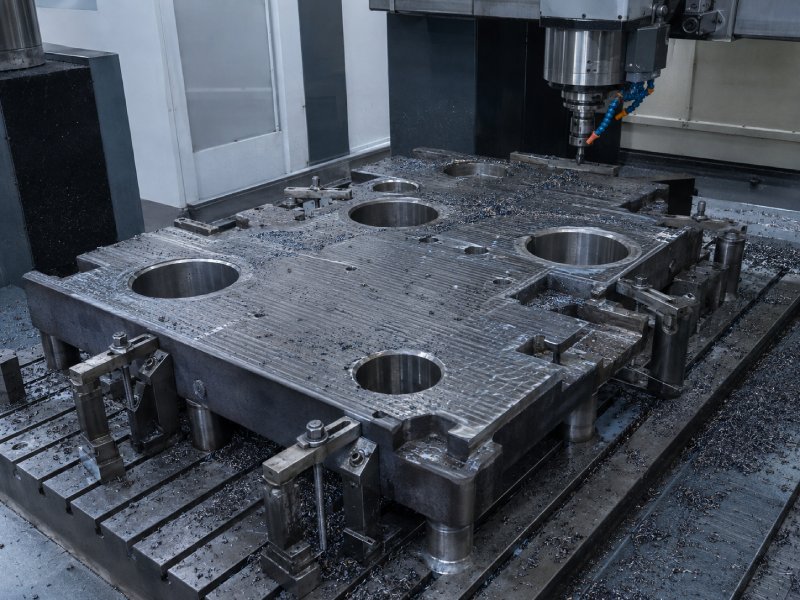
The Common Mistake: Finishing the Bore Too Early
A frequent but risky approach is to machine one surface, drill and finish the H7 bores, and then complete the remaining faces.
This sequence appears efficient because it reduces the number of setups. In practice, it can create several problems.
When the opposite surface or surrounding areas are machined, additional material is removed and the residual stress is redistributed again. The plate may deform after the H7 bore has already been completed.
As a result:
The bore diameter may remain within H7 tolerance, but its axis may no longer be perpendicular to the functional datum.
The bore center may shift relative to other features.
A plug gauge may pass, while the mating shaft or locating pin does not assemble correctly.
Reworking the bore may increase its diameter beyond the permitted tolerance.
Correcting the part with a bushing may not be allowed by the drawing or customer.
The problem is not necessarily poor boring or reaming accuracy. It is an incorrect machining sequence.
Step 1: Rough-Machine Both Sides
The first stage should remove most of the machining allowance while maintaining a relatively balanced material-removal strategy.
Instead of fully machining one side and leaving the other side untouched, both major faces should normally be rough-machined in stages. This helps release internal stress more evenly and reduces the risk of severe one-sided deformation.
During rough machining, the process should:
Leave sufficient allowance for later datum correction.
Avoid excessive clamping force.
Support the plate at appropriate locations.
Use a cutting strategy that limits localized heat.
Alternate machining between major surfaces when practical.
Leave all precision bores undersized.
At this stage, H7 features should only be drilled or rough-bored. Enough stock must remain for semi-finishing and final finishing after the workpiece becomes stable.
The exact allowance depends on the plate size, initial condition, bore diameter, geometric requirements, and expected deformation. A fixed allowance should not be applied to every large steel plate without evaluation.
Step 2: Allow the Workpiece to Stabilize
After rough machining, the plate should be unclamped and allowed to stabilize before precision features are completed.
Depending on the component and its requirements, stabilization may involve:
Natural aging between machining stages
Thermal stress-relief treatment
Controlled cooling after heavy machining
Intermediate dimensional inspection
Re-clamping the plate in a relaxed condition
This step is sometimes considered unproductive because the machine is not actively cutting the part. In reality, it can prevent much more expensive rework or complete part rejection later.
If stress-relief heat treatment is required, it should be evaluated before final tolerances are produced. Heat treatment performed after finishing the H7 bores may alter both their size and position.
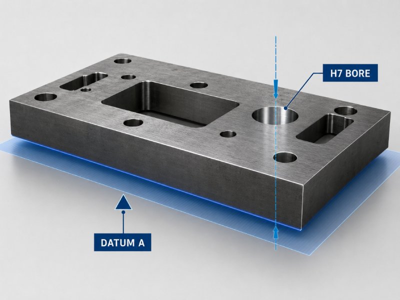
Step 3: Establish the Functional Datum
Once the plate has stabilized, the primary datum surface should be finish-machined or ground.
This surface becomes the reference for:
Bore position
Bore-axis perpendicularity
Opposite-face parallelism
Overall thickness
Inspection setup
Final assembly
This is the critical logic behind the entire machining plan:
A precision bore cannot have a reliable position or orientation until its datum is stable and accurate.
If the drawing defines a primary datum, the manufacturing setup should reproduce that functional reference as closely as possible. Selecting the most convenient clamping surface instead of the actual design datum can introduce inspection and assembly errors.
After the primary datum is established, secondary and tertiary datums can be created to control the remaining directions and remove ambiguity during positioning.
Step 4: Semi-Finish the H7 Bores
The H7 bores can now be semi-finished relative to the established datum system.
Semi-finishing serves several purposes:
Correcting drill-position error
Improving bore straightness
Removing uneven stock
Reducing the final cutting load
Confirming that sufficient finishing allowance remains
Identifying unexpected deformation before the final pass
For large precision bores, boring is generally more effective than relying only on drilling because the boring tool can correct the bore center and improve alignment.
Small H7 bores may be finished by reaming, while larger or more position-critical bores may require precision boring. The correct method depends on the diameter, bore depth, tolerance, surface-finish requirement, and machine rigidity.
Step 5: Side Drilling, Tapping, and Thread Milling
Side holes and threaded features can create additional forces, heat, and local stress changes. They should therefore be included in the process plan before the final inspection of the precision bores.
Depending on the feature geometry, these operations may include:
Side drilling
Rigid tapping
Thread milling
Counterboring
Spot-facing
Helical interpolation
Thread milling can be advantageous for larger threads, blind holes, expensive workpieces, or applications requiring better control of the thread fit. If a threading tool fails, it is also generally easier to recover the workpiece than after a broken tap.
However, thread milling is not automatically the best choice for every hole. Hole size, thread depth, production quantity, machine capability, and tool access must all be considered.
Step 6: Finish the H7 Bores
Final boring or reaming should be performed only after the datum surfaces are complete and the major stress-releasing operations have been finished.
Before the final cut, the machinist should confirm:
The plate is supported without rocking.
Clamping does not distort the workpiece.
The datum surface is clean and fully seated.
Bore stock is reasonably uniform.
Tool runout is controlled.
The workpiece and inspection instruments are at a stable temperature.
Tool wear and dimensional compensation have been evaluated.
The finishing method should be selected according to the bore’s functional requirements.
Precision Boring
Precision boring provides better control over bore location, straightness, and alignment. It is often preferred for large bores or features with strict positional and perpendicularity requirements.
Reaming
Reaming can efficiently achieve an accurate diameter and good surface finish, but it has limited ability to correct a significantly misplaced or misaligned hole. The pre-machined bore must already be accurate and contain a suitable, uniform allowance.
Bore Grinding or Honing
When requirements exceed normal milling-machine capability, bore grinding or honing may be considered. These processes can improve size, roundness, and surface finish, although they do not replace the need for a correct datum and process sequence.
Clamping Force Can Change the Inspection Result
Large plates are often flexible enough to deform under clamping pressure. A bore machined while the plate is forced flat may change its orientation after the clamps are released.
The workpiece should therefore be supported in its natural condition whenever possible. Low-force clamping, distributed support, and carefully selected clamping points can reduce artificial deformation.
If a plate must be restrained to represent its assembled state, the machining and inspection conditions should reflect the actual functional mounting condition. Otherwise, the supplier and customer may obtain different inspection results from the same part.
Quality Control Requires More Than a Go/No-Go Gauge
A plug gauge can confirm whether a bore accepts the correct limit sizes, but it cannot fully verify the functional condition of a large precision plate.
A complete inspection plan may include the following methods.
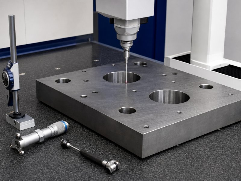
Bore Gauge or Internal Micrometer
A bore gauge or three-point internal micrometer can measure the actual bore diameter at different depths and directions. This helps identify:
Taper
Ovality
Barrel-shaped geometry
Bell-mouth conditions
Diameter variation along the bore
Measurements should be taken at several depths rather than only near the bore entrance.
Coordinate Measuring Machine
A CMM can evaluate the relationship between the bore and the defined datum system, including:
Bore-center position
Distance between multiple bores
Bore-axis orientation
Perpendicularity to the primary datum
Alignment with other functional features
The CMM setup should use the datums specified on the drawing. Creating an inspection alignment from convenient but non-functional surfaces can produce misleading results.
Flatness and Perpendicularity Verification
The datum surface must be inspected before it is used to evaluate the bores. If the datum itself is unstable or outside flatness tolerance, the resulting bore-position and perpendicularity data may not represent the component’s true condition.
Depending on the required accuracy, flatness may be checked using a CMM, surface plate and indicator, or other suitable metrology equipment.
Final Inspection Should Be Performed in a Relaxed Condition
After machining is complete, the plate should be unclamped, cleaned, deburred, and allowed to return to a stable temperature before final inspection.
Inspecting the component immediately after machining can produce inaccurate results because:
Cutting heat may temporarily change the bore diameter.
Clamping force may hold the plate in a distorted condition.
Chips or burrs may prevent correct datum contact.
Temperature differences between the part and measuring equipment may affect the result.
Final inspection conditions should be controlled, especially when the H7 tolerance band is narrow relative to the size and mass of the component.
A More Reliable Machining Sequence
A typical process route for a large C45 plate with H7 bores may be structured as follows:
Inspect the incoming material and confirm sufficient machining allowance.
Rough-machine the first major surface.
Turn the plate and rough-machine the opposite surface.
Rough-machine peripheral features and pre-drill the bores.
Unclamp the workpiece and allow it to stabilize.
Apply thermal stress relief if required.
Re-establish and finish the primary datum.
Finish the secondary and tertiary datum features.
Semi-finish the precision bores.
Machine side holes and threaded features.
Finish-bore or ream the H7 features.
Deburr, clean, and allow the component to reach inspection temperature.
Measure bore diameter at multiple depths and orientations.
Verify bore position and perpendicularity relative to the specified datums.
Record the final inspection results.
This sequence may require more setups than finishing the holes immediately, but it substantially reduces the risk of producing dimensionally acceptable bores on a geometrically incorrect plate.
The Engineering Lesson
For a large C45 steel plate, the H7 tolerance printed next to the bore is not the only requirement that matters.
The bore must remain correct relative to the surfaces and features that control assembly. That depends on residual-stress management, balanced material removal, workpiece stabilization, datum preparation, clamping strategy, and inspection alignment.
The most reliable principle is simple:
Rough first, stabilize the workpiece, establish the datum, and finish the precision bore last.
When the datum comes before the hole, the manufacturing process controls not only the bore diameter but also the feature’s true function in the finished assembly.
CUSTPARTS provides CNC machining support for large steel components, precision bores, robotic parts, and automation equipment components. Upload your drawings for a DFM review, machining assessment, and quotation.