

Threaded Hole Design for CNC Machining: 10 DFM Guidelines to Prevent Costly Mistakes
Threaded holes may look like simple features, but they are among the most common sources of manufacturing delays, inspection disputes, broken tools, and assembly failures in CNC-machined parts.
Problems often begin with incomplete drawing information, excessive thread depth, insufficient wall thickness, inaccessible hole locations, or a mismatch between the specified thread and the actual assembly requirement.
For robot components, automation equipment, fixtures, medical devices, and other precision assemblies, a poorly designed threaded hole can compromise the entire part—even when every other dimension is correct.
This guide explains ten practical design-for-manufacturability guidelines for creating reliable and cost-effective threaded holes in CNC-machined parts.
1. Specify the Complete Thread Standard
A thread callout should contain enough information for the manufacturer to select the correct cutting tool, inspection gauge, and machining process.
For metric threads, a complete specification may include:
Nominal thread diameter
Thread pitch
Tolerance class
Thread depth
Through-hole or blind-hole condition
Right-hand or left-hand direction
For example:
M6 × 1.0 – 6H, 12 mm minimum full thread
For inch threads, the callout may include:
1/4-20 UNC-2B, 0.50 in minimum full thread
Writing only “M6” may be insufficient when the design uses a non-standard pitch or requires a particular tolerance class.
Left-hand threads must also be clearly identified. For example:
M12 × 1.75 – LH
Never rely only on a 3D model color or a note elsewhere on the drawing to communicate the thread specification.
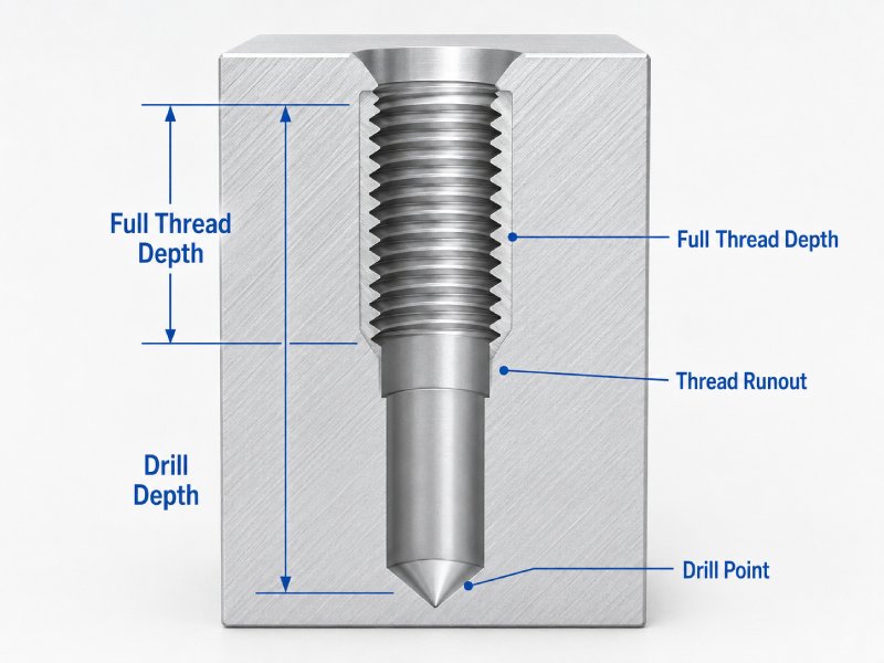
2. Distinguish Thread Depth from Drill Depth
In a blind tapped hole, thread depth and total drill depth are not the same.
The drill must normally extend deeper than the required full thread to provide space for:
The tapered lead of the tap
Incomplete threads near the bottom
Drill-point geometry
Chip accumulation
Tool clearance
If the drawing specifies a 15 mm thread depth in a hole that is only 15 mm deep, producing 15 mm of usable full thread may be impossible with a conventional tap.
A better drawing callout distinguishes between the two requirements:
Minimum full thread depth: 15 mm
Minimum drilled depth: 20 mm
The exact additional depth depends on the thread size, tool geometry, material, and machining method.
When bottom clearance is functionally critical, communicate the maximum permissible drill depth as well. This prevents the manufacturer from accidentally breaking through a thin wall or entering another internal feature.
3. Avoid Unnecessarily Deep Threads
A deeper thread does not automatically create a stronger connection.
In many applications, the first few engaged threads carry most of the load. Once adequate engagement has been achieved, additional thread depth may provide limited strength improvement while increasing machining difficulty.
Excessively deep threads can result in:
Longer machining cycles
Increased tap breakage risk
Poor chip evacuation
Higher tool wear
Greater difficulty maintaining thread quality
Increased inspection time
The required engagement depends on the internal and external thread materials, fastener grade, loading direction, vibration, and safety factor.
As a general design principle, determine the necessary engagement through engineering calculations instead of making every thread as deep as the surrounding geometry allows.
Soft materials such as aluminum and engineering plastics may require more engagement than hardened steel. If adequate engagement cannot be achieved, a threaded insert may be a more reliable solution.
4. Provide Adequate Edge Distance and Wall Thickness
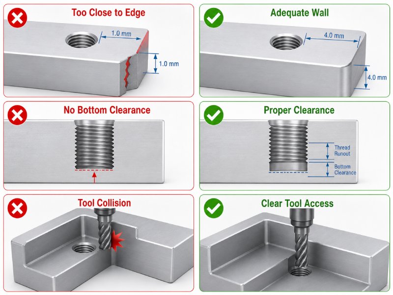
Placing a threaded hole too close to an edge can create a thin, weak wall between the thread and the outside surface.
This may cause:
Material breakout
Local deformation
Cracking during tapping
Distortion after anodizing or heat treatment
Reduced pull-out strength
Visible thread exposure on the side of the part
The required edge distance depends on the material, thread diameter, thread depth, loading, and manufacturing process.
Designers should evaluate the distance from the thread’s major diameter—not only from the modeled centerline—to the nearest edge, pocket, slot, or adjacent hole.
This is especially important for lightweight robot brackets and thin-wall automation components, where reducing weight often leaves limited material around threaded features.
If the available wall is too thin, possible alternatives include:
Moving the threaded hole
Reducing the thread diameter
Increasing the local boss thickness
Using a through-hole with a nut
Installing a threaded insert
Redesigning the joint geometry
5. Add an Entry Chamfer
A small chamfer at the entrance of a tapped hole provides several benefits.
It helps:
Guide the tap into the pilot hole
Remove the sharp edge after drilling
Improve screw alignment during assembly
Reduce the risk of cross-threading
Prevent the first thread from being raised above the surrounding surface
The chamfer should remove the sharp edge without eliminating excessive usable thread engagement.
If a large countersink is required for a flat-head screw, it should be specified separately from the thread-entry chamfer. A countersink and a small deburring chamfer are not interchangeable features.
For parts that will be anodized, plated, painted, or coated, the entry geometry should also account for coating buildup and assembly requirements.
6. Make Threaded Holes Accessible to Cutting Tools
A thread may be visible in a CAD model but still be difficult—or impossible—to machine with standard tools.
Common accessibility problems include:
Threads located deep inside narrow pockets
Holes positioned under overhangs
Angled holes without a suitable tool approach
Threads close to tall walls
Internal features that require excessive tool extension
Cross-holes with limited chip evacuation
Poor accessibility may require special tooling, multiple setups, electrical discharge machining, or a redesign of the part.
These solutions can significantly increase cost and lead time.
Before finalizing a design, check whether the drill and tapping tool can approach the hole along its axis without colliding with adjacent geometry.
For complex five-axis components, tool access may be improved through part orientation. However, five-axis capability should not be used to justify avoidable geometric restrictions. A simple design change is often more economical than an additional setup or custom tool.
7. Select the Right Threading Method
Different threaded-hole conditions may require different manufacturing methods.
Cut Tapping
A cutting tap removes material to create the thread. It is widely used and suitable for many metals and plastics.
Chip evacuation must be considered, especially in blind holes.
Form Tapping
A forming tap displaces material instead of cutting it. It creates no chips and can produce strong threads in suitable ductile materials.
However, form tapping requires a different pilot-hole diameter and is not appropriate for every material.
Thread Milling
Thread milling uses a rotating milling cutter to generate the thread.
Its advantages may include:
Better control in large or expensive parts
Lower risk of a broken tap becoming trapped in the component
Ability to machine different thread diameters with one tool
Easier adjustment of thread fit
Improved control in some difficult materials
Thread milling requires sufficient tool access and may take longer than tapping for small, high-volume holes.
Single-Point Threading
Internal threads in turned components may be produced on a CNC lathe using a single-point threading tool.
This approach is commonly used for larger internal diameters or non-standard thread profiles.
The correct method depends on the thread size, material, quantity, geometry, tolerance, and required reliability.
8. Account for Material and Surface Treatment
Thread performance changes with the base material and any post-machining treatment.
Aluminum
Aluminum is easy to machine, but threads may be vulnerable to wear, galling, or pull-out under repeated assembly.
Threaded inserts may be appropriate when:
Screws will be installed and removed repeatedly
High tightening torque is required
The joint experiences vibration
The aluminum is relatively soft
Long-term service reliability is critical
Stainless Steel
Stainless steel can work-harden and may create tapping difficulties if cutting parameters and lubrication are not properly controlled.
Galling between stainless steel internal and external threads should also be considered during assembly.
Engineering Plastics
Materials such as POM, PEEK, PEI, and nylon behave differently from metals. Thread strength may be affected by creep, temperature, moisture absorption, and repeated loading.
A metal insert may provide a more durable connection in frequently assembled plastic components.
Anodizing and Plating
Surface treatments can change the effective thread dimensions.
Hard anodizing, in particular, can create dimensional buildup that affects thread fit. Depending on the requirement, manufacturers may:
Mask the threads before treatment
Machine the threads after treatment
Compensate for coating thickness
Clean or chase the threads after treatment
The drawing should clearly specify whether the thread must remain conductive, coated, masked, or fully functional after finishing.
9. Define Critical Thread Inspection Requirements
A visual check is not sufficient when the thread is functionally important.
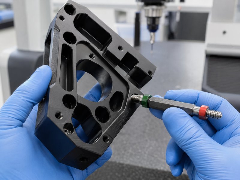
Internal threads are commonly verified using a calibrated GO/NO-GO thread plug gauge.
The GO gauge checks whether the thread can accept the allowable mating thread, while the NO-GO gauge helps identify an oversized or otherwise nonconforming thread condition.
Inspection requirements may also include:
Thread size and pitch verification
Minimum full thread depth
Thread position
Perpendicularity
Coaxiality
Surface condition
Functional assembly with a mating component
Insert installation depth
Torque or pull-out testing
A standard thread gauge does not verify every functional characteristic. For example, a thread may pass a plug gauge but still have incorrect position relative to a locating surface.
If thread location is critical to assembly, apply an appropriate positional tolerance and datum reference on the drawing.
For production orders, clarify whether every thread must be gauged or whether sampling inspection is acceptable.
10. Avoid Ambiguous CAD and Drawing Information
Threaded-hole problems frequently occur when the 3D model and 2D drawing communicate different information.
Typical examples include:
The drawing lists seven threads while a production note lists fourteen
Cosmetic thread graphics appear in the model but no thread callout exists
A hole is modeled at the tap-drill diameter without a thread designation
Thread depth is shown in one file but omitted in another
The model and drawing specify different pitches
An ordinary drilled hole is mistaken for a tapped hole
Mirrored parts accidentally retain right-hand threads instead of left-hand threads
The drawing should be treated as the controlled source for thread size, depth, tolerance, and inspection requirements unless otherwise agreed.
Before requesting a quotation, verify that:
Every threaded hole has a clear callout.
Quantities match the visible hole pattern.
Blind and through threads are identified.
Thread and drill depths are not confused.
Left-hand threads are explicitly marked.
Inserts are specified by type and installation requirement.
Surface-treatment instructions address the threads.
Critical thread positions have appropriate tolerances.
Threaded Inserts: When Should You Use Them?
Threaded inserts are often used in aluminum, magnesium, plastics, and other relatively soft materials.
They can improve:
Wear resistance
Pull-out strength
Resistance to repeated assembly
Repairability
Joint durability under vibration
However, an insert adds material cost, installation time, inspection requirements, and another potential source of dimensional error.
The drawing should specify:
Insert standard or manufacturer
Internal thread size
Insert length
Installation depth
Installation orientation
Locking requirement
Whether the insert is supplied by the customer or manufacturer
Inspection or torque requirements
Do not simply write “install Helicoil” unless that specific product and installation method are required. Different wire-thread, key-locking, and solid inserts have different hole-preparation requirements.
Common Threaded-Hole Drawing Mistakes
The following issues should be corrected before releasing a part for production:
Thread size shown without pitch
Missing thread depth
Thread depth equal to total blind-hole depth
Thread located too close to an edge
No room for the drill point
Excessive depth without a functional reason
Missing left-hand thread designation
Missing insert specification
Critical thread position without a datum reference
No instruction for threads after anodizing or plating
Conflicting information between the drawing and 3D model
Correcting these details during the design stage is much faster and less expensive than repairing or remanufacturing finished parts.
DFM Checklist for CNC-Machined Threads
Before submitting your files for quotation, confirm the following:
Is the thread standard fully specified?
Are pitch and tolerance class included where necessary?
Is the full thread depth clearly defined?
Is sufficient extra drill depth available?
Is the hole accessible to standard cutting tools?
Is there enough material around the thread?
Is the engagement length appropriate for the material?
Does the design require a threaded insert?
Will anodizing, plating, or coating affect thread fit?
Is the inspection method appropriate for the functional risk?
Do the 2D drawing and 3D model agree?
Conclusion
Reliable threaded holes require more than choosing a nominal thread size.
Thread depth, drill clearance, material strength, edge distance, tool access, surface finishing, tolerance, and inspection must all be considered together.
A clear and manufacturable thread design can reduce broken tools, additional setups, inspection disputes, assembly failures, and unexpected production costs.
CUSTPARTS provides CNC machining and DFM support for custom robot components, automation equipment parts, rapid prototypes, and low-volume precision production.
Upload your 2D drawings and 3D models for a manufacturing review and quotation. We can help identify thread-design risks before machining begins.