

Deep Pocket CNC Machining Design Guide: How to Reduce Vibration, Improve Accuracy, and Achieve Better Surface Finish
Meta Description: Learn how to design and machine deep pockets in CNC parts. This guide covers roughing strategies, step-down cutting, stock allowance, tool selection, corner finishing, semi-finishing, 5-axis machining, and DFM considerations.
Introduction
Deep pocket CNC machining is one of the most challenging operations in precision manufacturing.
Deep cavities and pockets are commonly found in:
Aerospace structural components
Robot parts and robotic systems
Automation equipment components
Medical devices
Precision housings
Lightweight aluminum structures
Industrial machinery components
Compared with conventional pocket milling, deep pocket machining creates additional manufacturing challenges because cutting tools must reach deeper areas while maintaining sufficient rigidity and machining stability.
Common challenges include:
Long tool overhang
Reduced cutting tool rigidity
Tool deflection
Increased vibration and chatter
Difficult chip evacuation
Heat accumulation
Poor surface finish
Dimensional deviation
Difficulty machining deep internal corners
Simply using a longer cutting tool is rarely the best solution.
A successful deep pocket CNC machining process requires the correct combination of part design, cutting tools, machining parameters, toolpaths, fixturing, roughing strategies, semi-finishing, and final finishing.
For this reason, deep pocket features should be carefully evaluated during the Design for Manufacturability (DFM) stage before CNC production begins.
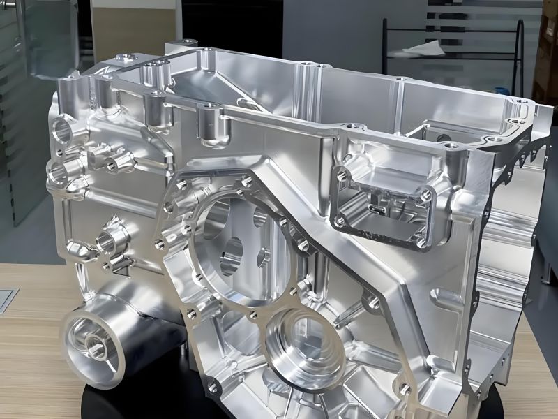
1. What Is Deep Pocket CNC Machining?
A deep pocket is generally a cavity where the machining depth is relatively large compared with the cutting tool diameter or pocket opening width.
Common deep pocket features include:
Pockets deeper than three times the tool diameter
Narrow and deep cavities
Deep internal walls
Deep ribs and slots
Lightweight structural pockets
Complex internal features
For example:
Tool diameter: Ø10 mm
Pocket depth: 50 mm
Depth-to-tool diameter ratio: 5:1
At this depth-to-diameter ratio, tool rigidity and machining stability become major concerns.
As tool extension increases, the risk of vibration, tool deflection, dimensional deviation, and poor surface finish also increases.
This is why deep pocket machining requires a different manufacturing strategy from conventional shallow pocket milling.
2. Why Is Deep Pocket CNC Machining Difficult?
The main challenge in deep pocket machining is maintaining cutting stability while the tool operates far away from the spindle and tool holder.
Long Tool Overhang
A longer tool extension reduces cutting tool rigidity.
This can cause:
Tool deflection
Cutting vibration
Chatter marks
Dimensional errors
Poor surface quality
Reduced cutting tool life
Whenever possible, the shortest suitable cutting tool should be used for each machining stage.
Difficult Chip Evacuation
Chips can accumulate at the bottom of deep cavities.
Poor chip evacuation may cause:
Chip recutting
Tool damage
Increased cutting temperature
Surface scratches
Unstable cutting conditions
Compressed air, coolant delivery, and optimized toolpaths can help remove chips from deep machining areas.
Heat Accumulation
Deep pockets provide limited space for heat dissipation.
Excessive cutting temperatures can affect:
Cutting tool life
Dimensional stability
Surface finish
Material deformation
This is especially important when machining stainless steel, titanium, and other difficult-to-machine materials.
Sudden Changes in Tool Engagement
When a cutting tool enters a deep internal corner, tool engagement can suddenly increase.
This causes higher cutting forces and increases the risk of:
Vibration
Tool deflection
Chatter
Tool breakage
For this reason, deep pocket corner machining requires carefully controlled cutting parameters and toolpaths.
3. Design Considerations for Deep Pocket CNC Parts
Good deep pocket machining begins with good part design.
Engineers should evaluate pocket depth, width, internal corner radius, wall thickness, and tool accessibility before finalizing the design.
Avoid Excessive Depth-to-Width Ratios
Very deep and narrow pockets significantly increase CNC machining difficulty.
A difficult design may include:
Narrow pocket openings
Excessive cavity depth
Thin surrounding walls
Small internal corner radii
When the functional requirements allow, consider:
Increasing the pocket opening width
Reducing unnecessary pocket depth
Increasing internal corner radii
Increasing wall thickness
Adding structural support ribs
Dividing extremely deep features into more machinable geometries
These design changes can reduce machining time, improve dimensional stability, and lower production costs.
4. Use Larger Internal Corner Radii Whenever Possible
Internal corner radius is one of the most important design considerations for deep pocket CNC machining.
Small corner radii require smaller cutting tools.
However, smaller tools have lower rigidity, especially when long tool extensions are required.
For example, machining a 50 mm deep pocket with a small-diameter end mill may create significant vibration and tool deflection.
Whenever the product design allows, use larger internal corner radii.
Benefits include:
Larger and more rigid cutting tools
Reduced machining vibration
Better surface finish
Improved dimensional accuracy
Longer cutting tool life
Shorter machining time
Designing realistic internal corner radii is one of the simplest ways to improve the manufacturability of deep pocket CNC parts.
5. Deep Pocket Rough Machining Strategy
The objective of rough machining is to remove large amounts of material efficiently while maintaining process stability.
Trying to machine the entire pocket depth in one operation can generate excessive cutting forces, vibration, and heat.
A better approach is progressive or layered roughing.
Step 1: Use Adaptive Roughing
Adaptive clearing or constant tool engagement strategies are highly effective for deep pocket machining.
These toolpaths help maintain a more consistent cutting load.
Benefits include:
Reduced cutting force variation
Improved tool life
Better chip evacuation
Lower vibration
More stable material removal
Instead of forcing the cutting tool directly into the full cavity depth, material should be removed progressively using controlled cutting engagement.
Step 2: Use Controlled Step-Down Cutting
Machining the pocket in multiple depth levels reduces cutting load and improves stability.
The appropriate step-down depends on:
Workpiece material
Cutting tool diameter
Tool extension length
Machine rigidity
Spindle performance
Coolant conditions
There is no single step-down value suitable for every deep pocket machining application.
The machining strategy should be adjusted according to the actual part geometry and production conditions.
6. Leave Controlled Stock Allowance After Roughing
Deep pockets should not normally be machined directly to final dimensions during roughing.
A controlled amount of material should remain for semi-finishing and final finishing.
Typical starting points may include:
Aluminum CNC Parts
Wall allowance: approximately 0.3–0.5 mm
Bottom allowance: approximately 0.3–0.5 mm
Steel and Stainless Steel CNC Parts
Wall allowance: approximately 0.5–1.0 mm
However, these values should not be treated as universal specifications.
The appropriate machining allowance depends on:
Part size
Pocket depth
Material
Wall thickness
Required tolerance
Cutting tool rigidity
Heat treatment conditions
Machining sequence
Leaving controlled stock allowance helps:
Protect final surfaces
Compensate for roughing deformation
Create consistent material conditions for finishing
Improve dimensional accuracy
Reduce finishing vibration
7. Tool Selection for Deep Pocket CNC Machining
Cutting tool selection directly affects machining stability, accuracy, surface finish, and production efficiency.
Use the Shortest Tool Possible
Long tool extensions increase the risk of:
Tool deflection
Cutting vibration
Chatter
Poor surface finish
Dimensional errors
A better machining strategy is to use different tool lengths for different pocket depths.
For example:
Short tool for upper-level roughing
Medium-length tool for intermediate depths
Long-reach tool only for the deepest machining areas
This approach improves cutting rigidity and reduces unnecessary tool overhang.
Use the Largest Practical Tool Diameter
Larger cutting tools generally provide greater rigidity.
When the part geometry allows, use the largest suitable tool for rough machining and switch to smaller tools only when machining corners or narrow features.
Select Cutting Tools According to Material
For aluminum deep pocket machining, suitable tools may include:
High-helix carbide end mills
Tools designed for efficient chip evacuation
Polished flute geometries
3-flute cutters for chip evacuation
Higher-flute-count tools when machining conditions and toolpaths permit
For stainless steel and harder materials, machining strategies generally require:
Rigid carbide tools
Stable cutting engagement
Controlled cutting parameters
Appropriate coolant delivery
Careful heat management
Tool selection should always consider the material, pocket geometry, depth, machine capability, and required surface quality.
8. Why Semi-Finishing Is Important for Deep Pockets
After rough machining, the remaining stock may not be perfectly uniform.
Roughing can also introduce:
Local deformation
Uneven material allowance
Residual tool marks
Dimensional variation
Performing final finishing immediately after roughing may cause inconsistent cutting loads.
A semi-finishing operation can help:
Equalize remaining stock
Remove roughing deformation
Improve geometric consistency
Reduce variation in final cutting forces
Prepare stable machining conditions for final finishing
Recommended operations may include:
Wall semi-finishing
Bottom semi-finishing
Corner pre-finishing
Remaining stock verification
The objective is to create a consistent and predictable material condition before the final finishing operation.
9. Deep Pocket Corner Cleaning Requires Special Attention
Deep internal corners are among the highest-risk areas in pocket machining.
When a cutting tool enters a corner, the engagement angle may increase significantly.
This can cause:
Increased cutting force
Tool deflection
Vibration
Chatter
Surface marks
Tool damage
For this reason, the same machining parameters used for open areas should not automatically be applied to deep corners.
Recommended strategies include:
Reducing feed rate
Controlling cutting speed when necessary
Reducing radial step-over
Using smooth tool entry and exit movements
Avoiding sudden changes in tool engagement
Using dedicated corner-cleaning toolpaths
Modern CAM software can also use rest machining strategies to identify material remaining from previous, larger cutting tools.
This allows smaller tools to remove only the necessary material instead of re-machining the entire pocket.
10. Use Rest Machining for Deep Pocket Corners
Rest machining is particularly useful for complex deep cavities.
The process typically includes:
Rough machining with a larger cutting tool
Identifying remaining material in corners
Using a smaller tool to remove only the residual material
Performing semi-finishing
Completing final precision finishing
Benefits include:
Reduced machining time
Lower tool wear
Better corner quality
More stable cutting conditions
Reduced unnecessary tool engagement
For complex robot components, automation equipment parts, and precision housings, rest machining can significantly improve CNC machining efficiency.
11. Final Finishing Strategy for Better Surface Quality
For high-precision deep pocket CNC parts, a single finishing operation may not provide the best results.
A more stable process can include two finishing stages.
Stage 1: Semi-Finish or Intermediate Finish
The objective is to:
Remove remaining rough machining marks
Equalize surface conditions
Improve geometric consistency
Prepare the part for precision finishing
Stage 2: Final Precision Finish
The final finishing operation should use:
Stable tool engagement
Controlled feed rates
Appropriate cutting speeds
Reduced cutting forces
Consistent toolpaths
Suitable coolant or air delivery
Benefits include:
Better surface roughness
Improved dimensional accuracy
Reduced visible tool marks
More consistent appearance
Improved repeatability
For parts with tight tolerances or specific surface roughness requirements, finishing parameters should be optimized according to the actual geometry and material.
12. Deep Pocket CNC Machining for Thin-Wall Parts
Deep pockets are often used to create lightweight components by removing large amounts of material.
However, this can leave thin walls and reduce part rigidity.
Common problems include:
Wall deformation
Cutting vibration
Dimensional instability
Part movement during machining
Deformation after unclamping
Recommended strategies include:
Symmetrical material removal
Progressive roughing
Controlled stock allowance
Reduced finishing forces
Optimized machining sequences
Proper fixture support
Allowing the part to stabilize between machining stages when necessary
Thin-wall deep pocket parts require careful coordination between part design, machining strategy, and fixture design.
13. Deep Pocket Machining With 5-Axis CNC
5-axis CNC machining can provide significant advantages for complex deep pocket parts.
By changing the cutting tool orientation, 5-axis machines can sometimes reduce the required tool extension length.
Potential benefits include:
Improved tool angle control
Reduced tool overhang
Better cutting rigidity
Improved access to complex features
Better chip evacuation
Reduced number of setups
Improved machining accuracy
5-axis machining is particularly suitable for:
Aerospace structural components
Robot components
Automation equipment parts
Complex aluminum structures
Precision housings
Parts with multiple deep cavities
However, not every deep pocket requires 5-axis machining.
A professional CNC machining supplier should evaluate whether 3-axis, 4-axis, or 5-axis machining provides the most efficient and cost-effective manufacturing solution.
14. Fixture Design for Deep Pocket CNC Parts
Fixture design is another critical factor in deep pocket machining.
As material is removed from the workpiece, the structural rigidity of the part may decrease.
Incorrect clamping can cause:
Part deformation
Machining vibration
Dimensional errors
Positioning instability
Deformation after unclamping
Possible fixture solutions include:
Custom soft jaws
Dedicated support fixtures
Multiple locating points
Sacrificial support structures
Vacuum fixtures for suitable thin components
The correct fixture strategy depends on the part geometry, material, wall thickness, machining sequence, and tolerance requirements.
Fixture planning should therefore be considered during the DFM review stage rather than after machining problems occur.
15. Common Deep Pocket CNC Machining Problems and Solutions
Problem: Excessive Vibration
Possible causes:
Excessive tool overhang
Small cutting tool diameter
Aggressive cutting parameters
Poor fixture rigidity
Possible solutions:
Reduce tool extension
Use a larger cutting tool
Optimize feed and speed
Reduce radial engagement
Improve workholding
Problem: Poor Surface Finish
Possible causes:
Tool deflection
Chatter
Chip recutting
Uneven finishing allowance
Possible solutions:
Add a semi-finishing operation
Improve chip evacuation
Reduce finishing forces
Use dedicated finishing tools
Maintain consistent stock allowance
Problem: Dimensional Inaccuracy
Possible causes:
Part deformation
Tool deflection
Thermal effects
Incorrect machining sequence
Possible solutions:
Optimize roughing and finishing sequences
Improve fixture support
Use semi-finishing
Allow sufficient stock for final machining
Inspect critical dimensions between machining stages when necessary
16. Deep Pocket CNC Machining DFM Checklist
Before starting production, engineers and CNC machining suppliers should evaluate the following questions:
Is the pocket depth functionally necessary?
Can the pocket opening be increased?
Can the internal corner radius be enlarged?
Can standard cutting tools reach the machining area?
Is excessive tool extension required?
Is sufficient stock allowance planned for finishing?
Can chips be effectively removed from the cavity?
Can the part be securely fixtured?
Will the part lose rigidity as material is removed?
Are roughing, semi-finishing, and final finishing operations properly separated?
Would 5-axis CNC machining reduce tool overhang or the number of setups?
Are critical tolerances and surface finish requirements clearly specified on the drawing?
Answering these questions during the DFM stage can prevent many deep pocket machining problems before production begins.
Conclusion
Deep pocket CNC machining requires a controlled manufacturing strategy rather than simply using longer tools or increasing cutting parameters.
A reliable deep pocket machining process may include:
Manufacturable pocket geometry
Larger internal corner radii where possible
Layered or adaptive rough machining
Controlled step-down cutting
Proper stock allowance
Rigid cutting tool selection
Effective chip evacuation
Stable semi-finishing operations
Dedicated corner cleaning
Intermediate finishing before final finishing
Optimized fixture design
5-axis machining when technically and economically appropriate
With proper DFM planning and CNC machining strategies, complex deep pocket components can achieve better dimensional accuracy, improved surface finish, reduced vibration, and more consistent production quality.
Precision Deep Pocket CNC Machining Services
Custparts provides precision CNC machining services for complex robot parts, automation equipment components, aerospace parts, precision housings, and custom mechanical components.
Our machining capabilities include:
3-axis CNC machining
4-axis CNC machining
5-axis CNC machining
Deep pocket and deep cavity machining
Thin-wall CNC machining
Complex aluminum machining
Stainless steel machining
Titanium machining
Engineering plastic machining
Prototype and low-volume production
DFM support
If your project includes deep cavities, long-reach machining, thin walls, tight tolerances, or complex internal features, send us your 2D drawings and 3D CAD files for a DFM review and CNC machining quotation.