

Deep Cavity CNC Machining Case Study: Long Tool Milling and Corner Cleaning
Introduction
Deep cavity CNC machining is commonly required for aerospace components, automation equipment, molds, robotics, precision instruments, and complex mechanical parts.
Unlike standard pocket milling, deep cavities create significant machining challenges because the cutting tool must reach far below the top surface of the workpiece.
As the machining depth increases, manufacturers may encounter problems such as:
Tool vibration and chatter
Tool deflection
Poor surface finish
Incomplete corner machining
Difficult chip evacuation
Heat accumulation
Dimensional deviation
Increased risk of tool breakage
These problems become more serious when the cavity contains narrow areas, small internal corner radii, or high aspect-ratio walls.
In this deep cavity CNC machining case study, we explain how a precision component with deep internal features was machined using long-reach cutting tools, multiple milling operations, corner cleaning strategies, and dimensional inspection.
The case demonstrates an important principle in precision CNC manufacturing:
Deep cavity machining requires more than simply using a longer cutting tool.
Successful production depends on the correct combination of tool selection, machining sequence, cutting parameters, chip evacuation, corner finishing, and inspection strategy.
1. Project Overview
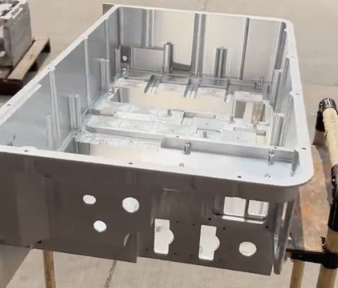
The component in this case study was a precision aluminum part containing several deep cavities and narrow internal features.
Part Characteristics
The main features included:
Multiple deep machined pockets
High cavity depth-to-width ratio
Narrow internal areas
Small corner radii
Thin sections between adjacent cavities
Tight dimensional tolerances
Surface finish requirements
Limited tool accessibility
The customer required the finished component to maintain dimensional accuracy while achieving clean internal walls and fully machined corner features.
The main manufacturing challenge was determining how to machine the deepest areas without excessive tool vibration or dimensional deviation.
2. Why Deep Cavity CNC Machining Is Difficult
Deep cavity machining becomes increasingly difficult as the cutting tool extends farther from the spindle or tool holder.
A longer tool overhang reduces machining rigidity.
When cutting forces act on the tool, the tool may bend slightly during machining. This phenomenon is known as tool deflection.
Even small amounts of tool deflection can cause:
Oversized or undersized features
Tapered cavity walls
Poor surface finish
Chatter marks
Uneven material removal
Premature tool wear
The relationship between tool length and rigidity is extremely important.
As tool overhang increases, machining stability decreases significantly.
For this reason, using the shortest possible cutting tool for each machining operation is one of the fundamental principles of deep cavity CNC machining.
3. Initial DFM Analysis
Before production began, our engineering team performed a DFM analysis of the customer’s CAD model and technical drawing.
The evaluation focused on several important factors.
Cavity Depth
The maximum machining depth was analyzed to determine the required tool reach.
Internal Corner Radius
The smallest internal radius determined the minimum cutter diameter required for corner finishing.
Tool Accessibility
The engineering team checked whether standard end mills could reach all internal surfaces.
Wall Thickness
Thin sections between cavities were evaluated for potential deformation during material removal.
Tolerance Requirements
Critical dimensions were identified so that the machining and inspection processes could be planned accordingly.
Surface Finish Requirements
Visible and functional surfaces were reviewed to determine whether additional finishing passes would be necessary.
This DFM evaluation helped identify the primary manufacturing risks before CNC programming began.
4. The Main Challenge: Long Tool Milling
The deepest sections of the component could not be machined using standard-length end mills.
Long-reach cutting tools were required.
However, simply replacing a standard tool with a longer tool would create several problems.
The longer tool could experience:
Increased vibration
Greater tool deflection
Reduced cutting stability
Poorer surface quality
Increased risk of tool breakage
Therefore, the machining process was divided into several stages.
Instead of using one long tool for the entire cavity, different tool lengths were used according to the machining depth.
This approach significantly improved process stability.
5. Rough Machining with Short and Rigid Tools
The first stage involved removing the majority of the material using short, rigid cutting tools.
Whenever possible, standard-length end mills were used.
Short tools provide several advantages:
Higher machining rigidity
Faster material removal
Reduced vibration
Longer tool life
Better dimensional stability
The objective of rough machining was not to achieve the final dimensions immediately.
Instead, the goal was to remove most of the material efficiently while leaving a controlled amount of machining allowance for later operations.
This strategy reduced the cutting load on the long-reach tools used during the deeper machining stages.
6. Progressive Machining Strategy
After the upper cavity areas were machined, progressively longer tools were introduced.
The machining sequence followed a depth-based strategy:
Short tool for upper cavity roughing
Medium-length tool for intermediate areas
Long-reach tool for deep sections
Smaller tool for internal corner cleaning
Finishing tool for critical surfaces
This method helped maintain machining rigidity throughout the process.
Using a long tool only where necessary is much more stable than machining the entire cavity with a long-reach cutter.
It also reduces cycle time and improves tool life.
7. Controlling Tool Vibration and Deflection
Tool vibration was one of the main risks in this project.
Several machining strategies were used to improve stability.
Minimize Tool Overhang
The tool extension was kept as short as possible for each operation.
Even small reductions in tool overhang can significantly improve machining rigidity.
Reduce Radial Cutting Engagement
Large radial cutting depths can generate excessive cutting forces.
Smaller radial engagement was used during deep milling operations to reduce tool deflection.
Optimize Axial Cutting Depth
The axial depth of cut was adjusted according to tool diameter, tool length, and machining conditions.
Control Feed Rate
Excessive feed rates can increase cutting forces and vibration.
The feed rate was optimized to maintain stable cutting conditions.
Maintain Consistent Tool Load
Sudden changes in cutting engagement can cause vibration.
The CNC toolpaths were optimized to maintain a more consistent cutting load.
Together, these strategies helped improve machining stability and reduce chatter.
8. Chip Evacuation in Deep Cavities
Chip evacuation is another major challenge in deep cavity CNC machining.
During standard milling operations, chips can easily leave the cutting area.
Inside a deep cavity, however, chips may become trapped.
Poor chip evacuation can cause:
Chip recutting
Tool damage
Scratched surfaces
Heat accumulation
Poor surface finish
Tool breakage
To reduce these risks, the machining process used controlled coolant delivery and air-assisted chip removal where appropriate.
The toolpath was also designed to provide sufficient space for chips to escape from the cutting area.
Regular chip evacuation was especially important during deep roughing operations.
9. Heat Control During Long Tool Milling
Heat accumulation can affect both tool life and dimensional accuracy.
Deep cavities restrict coolant access and airflow around the cutting zone.
As a result, heat may remain inside the cavity.
Excessive heat can cause:
Thermal expansion of the workpiece
Faster tool wear
Poor dimensional stability
Surface finish problems
The machining process therefore used appropriate coolant strategies and controlled cutting parameters.
In some operations, machining pauses or optimized toolpath sequences can also help prevent excessive local heat accumulation.
10. The Corner Cleaning Challenge
After the main cavity machining operations were completed, some internal corners still contained residual material.
This occurs because round cutting tools cannot create perfectly sharp internal corners.
The size of the remaining material depends on:
Tool diameter
Internal corner radius
Cavity depth
Tool accessibility
Machining direction
For this component, the corner areas required additional machining operations.
This process is commonly known as corner cleaning or rest machining.
11. Using Smaller Tools for Corner Cleaning
Smaller diameter end mills were used to remove the material remaining in the internal corners.
However, using smaller tools introduces additional challenges.
Small-diameter tools typically have:
Lower rigidity
Higher risk of breakage
Reduced material removal capability
Greater sensitivity to vibration
Longer machining cycles
Therefore, the smaller tools were only used where necessary.
The CNC programming software identified the remaining material from previous machining operations.
The smaller tool then machined only these areas.
This rest machining strategy reduced unnecessary cutting time and improved process efficiency.
12. Rest Machining Strategy
Rest machining is an important technique for complex CNC parts.
Instead of machining the entire cavity again with a smaller tool, the CAM software calculates where material remains after the previous operation.
The smaller cutter then removes only the remaining material.
This strategy provides several advantages:
Reduced machining time
Lower tool wear
Improved corner accuracy
Reduced risk of tool breakage
More efficient CNC programming
For deep cavity components, rest machining is especially useful because different tool diameters may be required at different machining stages.
13. Finishing the Deep Cavity Walls
After rough machining and corner cleaning, finishing operations were performed.
The objective was to achieve:
Final dimensional accuracy
Improved wall straightness
Better surface finish
Consistent cavity geometry
A small amount of machining allowance had been intentionally left during the roughing operations.
This material was removed during the finishing passes.
Using separate roughing and finishing operations provides better dimensional control than attempting to achieve final dimensions during heavy material removal.
14. Preventing Tapered Cavity Walls
Long tools may bend slightly under cutting forces.
This can cause the cavity wall to become tapered.
For example, the upper section of the wall may have the correct dimension while the deeper section shows dimensional deviation.
To reduce this problem, the machining strategy included:
Reduced cutting forces
Controlled finishing allowances
Multiple finishing passes
Optimized tool engagement
Stable tool holders
Appropriate cutting tools
Critical cavity dimensions were then verified during inspection.
15. Tool Selection for Deep Cavity Machining
Tool selection played an important role in the success of this project.
Several factors were considered.
Tool Diameter
Larger diameter tools provide greater rigidity.
Therefore, the largest possible cutter was used for each machining area.
Tool Length
The shortest tool capable of reaching the required depth was selected.
Tool Material
Carbide cutting tools were used to provide sufficient rigidity and wear resistance.
Tool Geometry
Cutting tool geometry was selected according to the workpiece material and machining conditions.
Tool Holder Stability
Stable tool holding is essential for long-reach machining.
Tool runout and holder rigidity can significantly affect machining performance.
16. CNC Programming Strategy
The CNC programming process was designed to balance machining efficiency and dimensional accuracy.
The main programming considerations included:
Progressive cavity machining
Controlled tool engagement
Optimized entry strategies
Reduced sudden cutting loads
Rest machining
Corner cleaning
Separate finishing operations
Toolpath simulation was performed before machining.
This helped identify potential problems such as:
Tool collisions
Holder interference
Insufficient tool reach
Unmachined areas
Excessive tool engagement
Simulation is particularly important for deep cavity components because tool and holder clearance may be limited.
17. Inspection of the Finished Component
After machining, the component underwent dimensional inspection.
Critical dimensions included:
Cavity depth
Cavity width
Internal wall position
Corner features
Hole locations
Overall part dimensions
Depending on the component geometry and tolerance requirements, inspection equipment may include:
Coordinate Measuring Machine (CMM)
Digital height gauge
Micrometers
Calipers
Depth gauges
Optical measurement equipment
Deep cavity inspection can also be challenging because some internal features are difficult to access.
Therefore, inspection feasibility should be considered during the DFM stage.
18. Final Machining Results
After optimizing the machining process, the component achieved the required dimensional and surface quality standards.
The final results included:
Stable deep cavity dimensions
Reduced tool vibration
Clean internal surfaces
Improved corner machining
Controlled wall accuracy
Acceptable surface finish
Consistent machining results
The progressive machining strategy significantly reduced the cutting load on the long-reach tools.
Corner cleaning operations successfully removed the residual material left by larger cutters.
The project demonstrated that deep cavity machining can achieve stable results when the machining process is properly planned.
19. Key Lessons from This Deep Cavity CNC Machining Case Study
Several important manufacturing lessons can be learned from this project.
Use the Shortest Possible Tool
Long tools should only be used when required by the machining depth.
Remove Most Material with Rigid Tools
Short and large-diameter tools should perform the majority of the rough machining.
Machine Deep Cavities Progressively
Different tool lengths should be used according to the machining depth.
Control Cutting Forces
Reduced radial engagement and optimized cutting parameters can improve stability.
Plan Chip Evacuation
Deep cavities require effective chip removal strategies.
Use Rest Machining for Corner Cleaning
Smaller tools should machine only the material that larger tools cannot reach.
Separate Roughing and Finishing Operations
Controlled finishing allowances help improve dimensional accuracy and surface quality.
20. DFM Recommendations for Deep Cavity CNC Parts
Product designers can improve manufacturability by considering several design recommendations.
Avoid Unnecessarily Deep Cavities
Increasing cavity depth increases machining difficulty and cost.
Increase Internal Corner Radii
Larger internal radii allow manufacturers to use larger and more rigid cutting tools.
Provide Tool Access
Ensure sufficient clearance for cutting tools and tool holders.
Avoid Extremely Narrow Deep Features
Narrow deep slots may require small-diameter long-reach tools, significantly increasing machining risk.
Specify Critical Tolerances Only Where Necessary
Applying tight tolerances to every cavity surface can increase manufacturing cost.
Consider Inspection Accessibility
Features that are difficult to machine may also be difficult to inspect.
Early communication between product designers and CNC manufacturers can help identify these problems before production.
21. How Deep Cavity Design Affects CNC Machining Cost
Several design factors can increase the cost of deep cavity machining.
These include:
Greater cavity depth
Smaller internal corner radii
Narrow machining areas
Tight tolerances
High surface finish requirements
Difficult tool access
Complex inspection requirements
Deep cavities often require:
More cutting tools
Longer machining cycles
Slower cutting parameters
Additional finishing operations
More complex CNC programming
Increased inspection time
Therefore, optimizing the component design before production can significantly reduce manufacturing cost.
22. When Is 5-Axis CNC Machining Useful for Deep Cavities?
Some deep cavity components may benefit from 5-axis CNC machining.
5-axis machining can allow the cutting tool to approach the component from different angles.
Potential advantages include:
Reduced tool overhang
Improved tool accessibility
Better machining rigidity
Fewer setups
Improved surface quality
Easier machining of complex cavity geometry
However, not every deep cavity component requires 5-axis machining.
The most suitable machining process depends on:
Component geometry
Cavity depth
Tool accessibility
Tolerance requirements
Production quantity
A professional CNC machining supplier should evaluate the component before selecting the manufacturing process.
23. Frequently Asked Questions About Deep Cavity CNC Machining
What is considered a deep cavity in CNC machining?
A deep cavity generally refers to a machined pocket or internal feature where the depth is large compared with the cavity width or cutting tool diameter.
The exact definition depends on the component geometry and machining conditions.
Why are long tools difficult to use?
Long tools have lower rigidity and are more sensitive to vibration and deflection.
This can affect dimensional accuracy, surface finish, and tool life.
How can tool vibration be reduced?
Tool vibration can be reduced by minimizing tool overhang, reducing cutting forces, optimizing cutting parameters, improving tool holding, and maintaining stable tool engagement.
Why is corner cleaning necessary?
Round cutting tools cannot completely machine small internal corners when the cutter diameter is larger than the required corner radius.
Smaller tools are therefore used to remove the remaining material.
What is rest machining?
Rest machining is a CNC programming strategy that allows a smaller tool to machine only the material left behind by a previous larger tool.
Can deep cavities achieve tight tolerances?
Yes.
However, achievable tolerance depends on cavity depth, tool accessibility, material, tool rigidity, machine capability, and inspection requirements.
How can designers reduce deep cavity machining costs?
Designers can reduce cost by increasing internal corner radii, avoiding unnecessary cavity depth, providing sufficient tool access, and specifying tight tolerances only on critical features.
Conclusion
Deep cavity CNC machining presents several manufacturing challenges, including long tool vibration, tool deflection, chip evacuation, heat accumulation, difficult corner machining, and dimensional control.
In this case study, the component was successfully machined using a progressive manufacturing strategy.
The process included:
Initial DFM analysis
Rough machining with short and rigid tools
Progressive use of longer cutting tools
Controlled cutting parameters
Optimized chip evacuation
Rest machining
Corner cleaning with smaller tools
Separate finishing operations
Final dimensional inspection
The key to successful deep cavity machining is not simply selecting a machine with sufficient travel or using a longer cutting tool.
It requires careful coordination between component design, cutting tools, CNC programming, machining parameters, workholding, and quality inspection.
If your CNC machined component contains deep pockets, narrow internal areas, small corner radii, or difficult-to-reach features, early DFM analysis can help identify manufacturing risks and optimize the machining process before production.
Need Deep Cavity CNC Machining Support?
If you are developing a precision component with deep cavities, complex internal features, or difficult tool access, our engineering team can review your CAD files and drawings before production.
We provide CNC machining services for prototypes and low-to-medium volume production, including:
Deep cavity CNC milling
Precision CNC machining
3-axis and 5-axis machining
Aluminum, stainless steel, titanium, and engineering plastics
Tight tolerance machining
Surface finishing
Dimensional inspection
DFM analysis
Send us your CAD files and technical drawings to receive a manufacturing review and CNC machining quotation.