

Thin-Wall Aluminum CNC Machining Case Study: Preventing Deformation
Meta Description:
Explore a thin-wall aluminum CNC machining case study and learn how optimized fixturing, machining sequences, cutting parameters, and inspection methods help prevent deformation and achieve stable dimensional accuracy.
Introduction
Thin-wall aluminum components are widely used in aerospace, robotics, automation equipment, optical systems, electronics, and precision instruments because they offer an excellent combination of lightweight construction, corrosion resistance, and machinability.
However, machining thin-wall aluminum parts presents significant manufacturing challenges.
When the wall thickness is small compared with the overall dimensions of the component, the part may have insufficient rigidity to resist cutting forces, clamping pressure, residual stress, and thermal deformation.
Common problems include:
Wall deformation
Part distortion after unclamping
Excessive vibration
Chatter marks
Poor surface finish
Dimensional instability
Difficulty maintaining tight tolerances
This thin-wall aluminum CNC machining case study explains how deformation risks can be controlled through DFM analysis, optimized fixturing, balanced material removal, appropriate cutting parameters, and careful inspection.
1. Project Overview
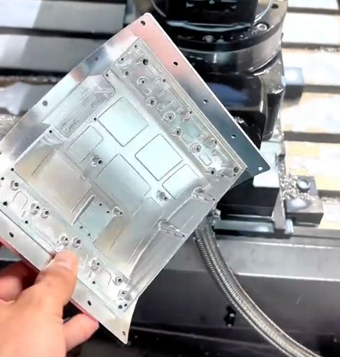
The project involved the CNC machining of a complex thin-wall aluminum component used in precision automation equipment.
The part featured:
Large internal pockets
Multiple thin-wall sections
Deep machining areas
Tight dimensional tolerances
High surface finish requirements
Multiple mounting and positioning features
The main manufacturing challenge was maintaining dimensional stability throughout the machining process.
Because a large amount of material had to be removed from the original aluminum stock, internal stress redistribution could cause the component to deform during machining or after being removed from the fixture.
Key Manufacturing Requirements
The project required careful control of:
Wall thickness
Flatness
Parallelism
Positional accuracy
Surface finish
Dimensional consistency
The machining strategy therefore had to focus not only on achieving the required dimensions but also on maintaining part stability throughout the entire manufacturing process.
2. Why Thin-Wall Aluminum Parts Are Difficult to Machine
Thin-wall aluminum parts behave differently from conventional rigid components during CNC machining.
As material is removed, the structural rigidity of the part gradually decreases.
Several factors can contribute to deformation.
Cutting Forces
When the cutting tool contacts a thin wall, radial and axial cutting forces may cause the wall to deflect.
The wall may temporarily move away from the cutting tool and return after the tool passes.
This can result in:
Dimensional errors
Uneven wall thickness
Poor surface finish
Tolerance deviations
Clamping Pressure
Excessive fixture pressure can deform the component before machining even begins.
The CNC machine may cut the part accurately while it is clamped, but once the fixture is released, the component may return toward its original shape.
This phenomenon can cause unexpected dimensional deviations after machining.
Residual Stress
Aluminum stock may contain internal residual stresses created during:
Rolling
Extrusion
Forging
Heat treatment
Material processing
Removing large amounts of material can redistribute these stresses and cause the part to distort.
Heat Accumulation
Although aluminum has good thermal conductivity, improper machining parameters can still generate localized heat.
For thin-wall components, even small temperature changes may affect dimensional stability during precision machining.
3. DFM Analysis Before CNC Machining
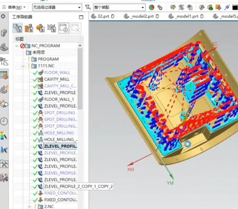
Before production started, the engineering team performed a detailed Design for Manufacturability analysis.
The objective was to identify potential deformation risks before programming and machining.
The DFM review focused on:
Wall thickness distribution
Pocket depth
Tool accessibility
Clamping locations
Datum selection
Machining sequence
Tolerance requirements
Inspection methods
One important consideration was determining which features should be machined first and which areas required additional material support during rough machining.
Instead of immediately machining all features to their final dimensions, additional material was intentionally left on critical surfaces.
This provided temporary structural support during the early machining stages.
4. Selecting the Right Aluminum Material
Material selection can significantly affect the dimensional stability of thin-wall CNC machined parts.
Common aluminum alloys used for precision CNC machining include:
Aluminum 6061-T6
Aluminum 6082-T6
Aluminum 7075-T6
For thin-wall components, material condition and internal stress should be considered in addition to mechanical properties.
Using stable, high-quality aluminum stock can reduce the risk of unexpected distortion during machining.
For particularly demanding components, stress-relieved material may be considered when dimensional stability is critical.
5. Optimizing the CNC Machining Sequence
The machining sequence was one of the most important factors in preventing deformation.
A conventional strategy of machining one area completely before moving to another could create uneven stress distribution.
Instead, the part was machined progressively.
Step 1: Rough Machining
The majority of the excess material was removed while leaving sufficient machining allowance on critical surfaces.
The objective was to create the basic geometry without reducing the structural rigidity too quickly.
Step 2: Semi-Finishing
After rough machining, additional material was gradually removed from both sides and critical areas.
This helped balance internal stress and reduced the risk of localized deformation.
Step 3: Intermediate Inspection
Critical dimensions and deformation conditions were checked before final machining.
This allowed the machining strategy to be adjusted if dimensional movement was detected.
Step 4: Finish Machining
Final dimensions were achieved using light cutting passes and optimized tool paths.
The reduced cutting forces during finishing helped minimize wall deflection and improve dimensional accuracy.
This progressive machining approach can be summarized as:
Rough Machining → Stress Redistribution → Semi-Finishing → Inspection → Finish Machining
6. Fixture Design for Thin-Wall Aluminum Parts
Fixture design plays a critical role in thin-wall CNC machining.
The fixture must hold the component securely without introducing excessive deformation.
For this project, the workholding strategy focused on:
Supporting rigid areas of the component
Avoiding excessive clamping pressure
Distributing clamping forces evenly
Providing support near thin-wall sections
Maintaining repeatable positioning
Avoiding Excessive Clamping Force
Applying more clamping pressure does not necessarily improve machining stability.
For thin-wall components, excessive pressure may create more dimensional problems.
The objective is to use sufficient force to prevent movement while minimizing artificial deformation.
Increasing Contact Area
Increasing the fixture contact area can help distribute clamping forces more evenly.
This reduces localized pressure and improves part stability.
Supporting Critical Areas
Temporary supports or customized fixtures can be used near flexible sections.
These supports help resist cutting forces during machining.
7. Tool Selection and Cutting Strategy
Tool selection directly affects cutting forces, vibration, and surface finish.
For thin-wall aluminum machining, the cutting tools should provide:
High sharpness
Low cutting resistance
Efficient chip evacuation
Stable cutting performance
Suitable tool rigidity
Sharp carbide cutting tools are commonly used for precision aluminum machining.
The tool diameter should also be carefully selected.
A larger tool may provide better rigidity, but excessive cutting forces can increase wall deflection.
A smaller tool may reduce cutting forces but could introduce tool vibration or longer machining times.
The correct balance depends on the geometry of the component.
8. Optimizing Cutting Parameters
Aggressive machining parameters can increase productivity when machining rigid components.
However, thin-wall parts require a different approach.
The machining parameters were optimized to reduce cutting forces and heat generation.
Important parameters included:
Spindle speed
Feed rate
Axial depth of cut
Radial depth of cut
Tool engagement
Cutting direction
During finish machining, light cutting passes were used to minimize wall deflection.
Stable tool engagement was also maintained to avoid sudden changes in cutting forces.
9. Using Balanced Material Removal
One of the key strategies for controlling deformation was balanced material removal.
Removing a large amount of material from only one side of the component can create uneven internal stress distribution.
Instead, material was removed progressively from different areas of the part.
This helped maintain structural balance during machining.
For complex thin-wall components, balanced material removal can significantly reduce:
Warping
Twisting
Flatness errors
Dimensional instability
The machining sequence should therefore consider the entire structural behavior of the component rather than individual features alone.
10. Managing Heat During Machining
Temperature control is another important consideration in precision thin-wall machining.
Heat can come from:
Cutting friction
Tool wear
High spindle speeds
Poor chip evacuation
Insufficient coolant
Effective cooling and chip removal help maintain stable machining conditions.
For this project, the machining process focused on maintaining consistent temperatures and preventing localized heat accumulation.
Stable thermal conditions helped improve dimensional repeatability during final machining.
11. Preventing Vibration and Chatter
Thin walls have lower structural rigidity and are therefore more susceptible to vibration.
Machining vibration can cause:
Chatter marks
Poor surface finish
Dimensional errors
Reduced tool life
Several strategies were used to control vibration:
Reducing tool overhang
Using rigid tool holders
Optimizing spindle speed
Controlling radial cutting engagement
Using sharp cutting tools
Supporting flexible areas
Applying light finishing passes
Tool paths were also designed to maintain smooth and consistent cutting conditions.
Sudden tool engagement was avoided whenever possible.
12. Precision Inspection During Production
Inspection is particularly important for thin-wall CNC machined components because dimensions may change during different manufacturing stages.
The inspection process included both in-process and final inspection.
Depending on the tolerance and geometry requirements, inspection equipment may include:
Coordinate Measuring Machines (CMM)
Height gauges
Micrometers
Calipers
Surface roughness testers
Custom inspection fixtures
Critical dimensions were inspected after semi-finishing and again after final machining.
This helped verify whether deformation occurred during the manufacturing process.
13. Inspection After Removing the Part from the Fixture
A critical mistake in thin-wall machining is checking dimensions only while the component remains clamped.
A part may appear dimensionally correct inside the fixture but deform after the clamping pressure is released.
For this reason, final inspection should be performed under controlled conditions after the part has been removed from the fixture.
This provides a more accurate evaluation of:
Flatness
Parallelism
Wall position
Overall dimensional stability
For high-precision applications, the component may also require sufficient stabilization time before final inspection.
14. Final Machining Results
By combining DFM analysis, optimized fixturing, balanced material removal, controlled cutting parameters, and multi-stage inspection, the deformation risks were successfully reduced.
The final component achieved:
Stable wall geometry
Improved dimensional consistency
Controlled flatness
Good surface finish
Reduced machining vibration
Repeatable production quality
The project demonstrated that successful thin-wall aluminum machining depends on the entire manufacturing process rather than a single machining technique.
15. Key Lessons from This Thin-Wall CNC Machining Case Study
Several important lessons can be learned from this project.
1. Analyze Deformation Risks Before Machining
Potential deformation problems should be identified during the DFM stage.
2. Do Not Remove Too Much Material at Once
Progressive machining helps maintain structural stability.
3. Optimize Fixture Pressure
The fixture should secure the part without introducing unnecessary deformation.
4. Use Balanced Material Removal
Removing material strategically can reduce stress-related distortion.
5. Control Cutting Forces
Sharp tools, appropriate parameters, and light finishing passes help minimize wall deflection.
6. Inspect the Part During Multiple Manufacturing Stages
Intermediate inspection can identify dimensional movement before final machining.
7. Perform Final Inspection After Unclamping
The true dimensional condition of a thin-wall component should be verified after fixture forces are removed.
16. How to Reduce Deformation in Thin-Wall Aluminum CNC Machining
For engineers designing thin-wall aluminum components, the following recommendations can improve manufacturability:
Avoid unnecessarily thin walls
Maintain consistent wall thickness whenever possible
Add corner radii to improve structural rigidity
Avoid excessive pocket depth
Define realistic tolerance requirements
Identify critical dimensions clearly on engineering drawings
Consider machining accessibility during part design
Discuss potential deformation risks with the CNC supplier before production
Early communication between design engineers and manufacturing engineers can prevent costly machining problems.
Conclusion
Thin-wall aluminum CNC machining requires careful control of cutting forces, fixture pressure, residual stress, vibration, and temperature.
In this case study, deformation was minimized through a combination of:
DFM analysis
Progressive machining
Balanced material removal
Optimized fixture design
Appropriate tool selection
Controlled cutting parameters
In-process inspection
Final inspection after unclamping
The most important lesson is that thin-wall machining accuracy is achieved through a complete manufacturing strategy.
For complex aluminum components with thin walls, deep pockets, tight tolerances, or demanding dimensional requirements, early DFM analysis can help identify manufacturing risks and develop a more stable CNC machining process before production begins.
Need Help with a Thin-Wall Aluminum CNC Machining Project?
If your project involves thin-wall aluminum parts, complex geometries, tight tolerances, or deformation risks, our engineering team can review your drawings and 3D models before production.
We provide precision CNC machining services for prototypes and low-to-medium volume production, including DFM analysis, fixture development, machining process optimization, surface finishing, and dimensional inspection.
Send us your CAD files, drawings, material requirements, quantities, and tolerance specifications to request a CNC machining quotation and DFM review.