

5-Axis CNC Machining Case Study: Complex Aluminum Robot Component
Introduction
Modern robotic systems require increasingly complex mechanical components with high dimensional accuracy, lightweight structures, and multiple functional features.
These components often include:
Complex 3D surfaces
Multiple machining angles
Deep pockets
Precision holes
Thin walls
Tight geometric tolerances
High surface finish requirements
Producing these parts with conventional 3-axis CNC machining may require multiple setups, complex fixtures, and repeated repositioning.
Each additional setup can introduce new sources of machining error.
For this reason, 5-axis CNC machining is widely used for complex aluminum robot components that require high precision and efficient production.
In this case study, we examine the manufacturing process of a complex aluminum component used in robotic automation equipment.
The project demonstrates how part geometry, machining strategy, fixture design, cutting tools, dimensional inspection, and 5-axis machining technology work together to achieve stable manufacturing quality.
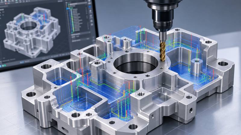
1. Project Overview
The customer required a precision aluminum component for a robotic automation system.
The part was designed as a structural and functional component connecting several mechanical assemblies.
The component included multiple complex machining features:
Multi-angle mounting surfaces
Precision positioning holes
Deep pockets
Internal corners
Threaded holes
Complex external geometry
Tight dimensional tolerances
Critical geometric relationships between different surfaces
The main project requirements included:
| Requirement | Specification |
|---|---|
| Material | Aluminum Alloy |
| Manufacturing Process | 5-Axis CNC Machining |
| Part Type | Complex Robot Component |
| Production Volume | Low-Volume Production |
| Dimensional Accuracy | Tight Tolerance Machining |
| Surface Requirement | Precision Machined Finish |
| Inspection | Dimensional and Geometric Inspection |
Although the component could theoretically be produced using conventional CNC machining methods, multiple setups would significantly increase production complexity.
Therefore, our engineering team evaluated the part during the DFM stage and selected a 5-axis CNC machining strategy.
2. The Main Manufacturing Challenges
Before machining began, our engineering team analyzed the 3D model and technical drawings.
Several manufacturing challenges were identified.
2.1 Complex Multi-Angle Geometry
The robot component contained machining features located on multiple surfaces and at different angles.
These features included:
Mounting holes
Positioning surfaces
Threaded holes
Angled structures
Complex pockets
Using a 3-axis CNC machine would require the workpiece to be repositioned several times.
For example, the machining process might require:
Machining the top surface
Repositioning the workpiece
Machining the side features
Repositioning again
Machining the angled surfaces
Performing additional setups for holes and threads
Every time the workpiece is repositioned, a new coordinate system must be established.
This increases the risk of:
Positioning errors
Datum inconsistencies
Geometric tolerance deviation
Longer setup time
5-axis CNC machining allows the cutting tool to access multiple surfaces during fewer setups.
This improves machining consistency and reduces cumulative positioning errors.
2.2 Maintaining Geometric Accuracy Between Multiple Features
One of the most important requirements was maintaining accurate relationships between different machined surfaces.
For robotic components, individual dimensions are not the only consideration.
The geometric relationship between features can be equally important.
Examples include:
Hole position relative to the datum
Perpendicularity between mounting surfaces
Parallelism between functional surfaces
Position accuracy between multiple holes
Angular relationships between machined features
If each surface is machined in a separate setup, positioning errors may accumulate.
Even when individual dimensions meet the drawing tolerance, the overall assembly may still experience problems.
Possible problems include:
Assembly misalignment
Increased mechanical friction
Poor movement accuracy
Uneven loading
Reduced equipment performance
By machining multiple critical features in the same setup, 5-axis machining helps maintain more consistent geometric relationships.
3. Why 5-Axis CNC Machining Was Selected
The main advantage of 5-axis CNC machining for this project was not simply machining speed.
The primary objective was to reduce setups and improve manufacturing consistency.
3.1 Fewer Machining Setups
Traditional 3-axis machining would require multiple fixtures and repositioning operations.
5-axis machining allowed our engineers to machine several surfaces within the same coordinate system.
This reduced:
Setup operations
Fixture changes
Manual repositioning
Coordinate recalibration
Potential positioning errors
Fewer setups can significantly improve manufacturing stability for complex precision components.
3.2 Better Tool Accessibility
Complex robot components often contain features that are difficult to reach with conventional cutting tools.
5-axis machining allows the workpiece or cutting tool to rotate during machining.
This provides better access to:
Angled surfaces
Deep pockets
Complex contours
Side features
Difficult machining areas
Better tool accessibility also allows engineers to select more appropriate cutting tools.
3.3 Shorter Cutting Tools
Tool rigidity is an important factor in precision CNC machining.
Long cutting tools are more susceptible to:
Vibration
Tool deflection
Reduced surface quality
Dimensional deviation
Because 5-axis machines can adjust the machining angle, shorter cutting tools can often be used.
Higher tool rigidity can improve:
Dimensional accuracy
Surface finish
Cutting stability
Tool life
This was particularly important for the deep pockets and complex surfaces of the robot component.
4. DFM Analysis Before Production
Before programming the CNC machine, our engineering team performed a detailed Design for Manufacturing analysis.
The DFM review focused on several important areas.
4.1 Datum Selection
A stable machining datum is essential for complex CNC components.
The datum must support:
Accurate workpiece positioning
Reliable inspection
Consistent machining coordinates
Stable production repeatability
Our engineers selected the primary machining datum based on the functional surfaces of the component.
Critical features were then machined relative to the same coordinate system whenever possible.
This helped reduce tolerance accumulation between multiple machining operations.
4.2 Tool Accessibility Analysis
The 3D model was analyzed to determine whether cutting tools could safely access all machining areas.
The engineering team evaluated:
Tool angle
Tool length
Holder interference
Machine travel
Workpiece rotation
Fixture interference
Collision analysis was performed during CNC programming.
This is particularly important for 5-axis machining because the cutting tool, spindle, workpiece, and fixture may move simultaneously.
4.3 Internal Corner Analysis
Some internal corners of the component were designed with small radii.
However, smaller internal corner radii require smaller cutting tools.
Small cutting tools may create several manufacturing problems:
Lower tool rigidity
Longer machining time
Increased tool wear
Higher risk of tool breakage
Where design modifications were possible, larger internal corner radii were recommended.
This allowed larger and more rigid cutting tools to be used.
4.4 Deep Pocket Machining Analysis
The component included several deep pocket structures.
Deep pockets are challenging because they may cause:
Tool vibration
Chip evacuation problems
Heat accumulation
Tool deflection
Poor surface finish
The machining strategy was therefore optimized using:
Appropriate tool length
Progressive material removal
Controlled cutting depth
Optimized tool paths
Effective coolant application
5. Raw Material Preparation
The component was manufactured from aluminum alloy.
Aluminum is widely used for robotic and automation components because it provides a good combination of:
Low weight
Good machinability
Corrosion resistance
Dimensional accuracy
Mechanical performance
However, aluminum components may still experience deformation if excessive internal stress is released during machining.
The raw material size was therefore selected with sufficient machining allowance.
Before precision finishing, most of the excess material was removed during rough machining.
6. Rough Machining Strategy
The objective of rough machining was to remove the majority of the raw material efficiently while maintaining sufficient material for finishing operations.
The rough machining process included:
External material removal
Pocket machining
Preliminary contour machining
Initial hole preparation
A balanced machining strategy was used.
Removing too much material from one area can create uneven stress distribution.
This may cause the component to deform after being removed from the fixture.
Therefore, material was removed progressively.
Adequate finishing allowance was maintained on critical surfaces.
7. Semi-Finishing and Stress Control
After rough machining, the component entered the semi-finishing stage.
The purpose of semi-finishing was to:
Remove remaining excess material
Improve dimensional consistency
Prepare surfaces for final machining
Reduce the effect of material deformation
For complex precision components, machining directly from raw material to final dimensions is not always the best strategy.
A more stable process is:
Rough Machining → Semi-Finishing → Precision Finishing
This approach allows the material to release machining stress gradually.
It also gives engineers an opportunity to verify dimensional conditions before final machining.
8. 5-Axis Precision Finishing
The final machining stage focused on the critical dimensions and functional surfaces.
The 5-axis CNC machine allowed multiple features to be machined within fewer setups.
The finishing process included:
Precision surface machining
Hole machining
Thread machining
Complex contour finishing
Angled feature machining
Critical datum surface finishing
Cutting parameters were optimized based on:
Tool diameter
Tool length
Cutting depth
Spindle speed
Feed rate
Surface finish requirements
The machining sequence was carefully controlled to minimize deformation and maintain dimensional stability.
9. Tool Selection for Complex Aluminum Machining
Tool selection directly affects machining accuracy and surface quality.
Several types of cutting tools were used during the project.
Flat End Mills
Flat end mills were used for:
Flat surfaces
Pockets
General material removal
Ball Nose End Mills
Ball nose tools were used for:
Complex 3D surfaces
Curved profiles
Surface finishing
Drills
Precision drilling tools were used for hole machining.
Threading Tools
Thread milling or tapping operations were selected depending on the thread size and design requirements.
The engineering team also considered:
Tool rigidity
Tool reach
Tool holder interference
Cutting edge geometry
Using the correct tool is essential for maintaining stable machining conditions.
10. Fixture Design and Workholding Strategy
Even with advanced 5-axis CNC machines, fixture design remains an important factor.
The fixture must hold the component securely without causing deformation.
The workholding strategy considered:
Clamping force
Workpiece rigidity
Tool accessibility
Machine rotation
Datum stability
Excessive clamping force may deform aluminum components.
Insufficient clamping force may allow movement during machining.
Therefore, the fixture was designed to provide stable support while maintaining access to multiple machining surfaces.
11. Preventing Collision During 5-Axis Machining
Collision prevention is a critical part of 5-axis CNC programming.
Potential collision areas include:
Cutting tool and workpiece
Tool holder and workpiece
Spindle and fixture
Machine table and workpiece
Before production, the machining program was simulated.
The simulation process verified:
Tool paths
Machine movement
Tool orientation
Fixture clearance
Machining sequence
This reduced production risk before the actual machining process began.
12. Dimensional Inspection
After machining, the component was inspected according to the technical drawing requirements.
Inspection focused on critical dimensions and geometric features.
The inspection process included:
Overall dimensions
Hole diameters
Hole positions
Surface relationships
Critical tolerances
Thread inspection
Depending on the feature requirements, inspection equipment may include:
Calipers
Micrometers
Height gauges
Bore gauges
Thread gauges
Coordinate Measuring Machines (CMM)
For complex robot components, CMM inspection is particularly useful because it can verify the geometric relationship between multiple features.
13. Surface Quality Inspection
Surface quality was also evaluated after machining.
Typical surface defects may include:
Tool marks
Scratches
Burrs
Chatter marks
Uneven surfaces
The machining process was optimized to achieve stable surface quality.
After CNC machining, the component was also inspected for burrs and sharp edges.
Deburring operations were performed where required.
14. The Final Manufacturing Result
By using a 5-axis CNC machining strategy, the complex aluminum robot component was successfully manufactured with stable dimensional and geometric accuracy.
The final manufacturing process achieved several important objectives:
Reduced machining setups
Improved feature positioning accuracy
Better tool accessibility
Stable machining of complex geometry
Improved surface quality
Reduced cumulative positioning errors
Reliable dimensional inspection
The project demonstrated that selecting the correct machining strategy is essential for complex robotic components.
Advanced CNC equipment alone does not guarantee high-quality results.
Successful precision machining requires the combination of:
Part Design + DFM Analysis + Machine Capability + Tool Selection + Fixture Design + Machining Strategy + Quality Inspection
15. 3-Axis vs 5-Axis Machining for Complex Robot Components
| Factor | 3-Axis CNC Machining | 5-Axis CNC Machining |
|---|---|---|
| Number of Setups | More | Fewer |
| Complex Geometry | Limited | Excellent |
| Angled Features | Multiple Repositioning Operations | Easier Machining Access |
| Tool Length | Often Longer | Shorter Tools Possible |
| Geometric Accuracy | More Setup-Related Variation | Better Feature Relationships |
| Fixture Complexity | Higher for Complex Parts | Can Be Reduced |
| Programming Difficulty | Lower | Higher |
| Machine Cost | Lower | Higher |
| Best Application | Simple Components | Complex Precision Components |
5-axis CNC machining is not always necessary.
Simple parts can often be produced more economically using 3-axis CNC machines.
However, when components contain complex geometry, multiple machining angles, or critical geometric relationships, 5-axis machining may provide better manufacturing efficiency and accuracy.
16. Key Lessons From This 5-Axis CNC Machining Project
This project demonstrates several important principles for manufacturing complex robot components.
Reduce Setups Whenever Possible
Every additional setup introduces potential positioning variation.
Machining more critical features within the same coordinate system can improve consistency.
Analyze Manufacturability Before Production
DFM analysis helps identify:
Difficult machining areas
Tool accessibility problems
Fixture limitations
Potential deformation risks
Early engineering evaluation can prevent expensive production problems.
Tool Rigidity Matters
Shorter and more rigid tools generally provide better machining stability.
5-axis machining can improve tool accessibility and allow more appropriate tool selection.
Control Material Removal
Balanced rough machining and semi-finishing strategies can reduce deformation.
This is particularly important for lightweight aluminum components.
Inspection Must Match Part Complexity
Complex parts require appropriate inspection methods.
Critical geometric relationships may require CMM inspection rather than conventional measuring tools.
17. When Should You Use 5-Axis CNC Machining?
5-axis CNC machining may be suitable when your component includes:
Complex 3D geometry
Multiple angled surfaces
Deep cavities
Difficult tool access
Critical hole positioning
Tight geometric tolerances
Multiple machining surfaces
High precision requirements
However, the decision should not be based only on part complexity.
Engineers should also consider:
Production quantity
Material
Tolerance requirements
Surface finish
Inspection requirements
Manufacturing cost
A professional CNC machining supplier should evaluate these factors during the DFM stage.
Conclusion
Complex aluminum robot components require more than advanced CNC machines.
Successful manufacturing depends on understanding the relationship between part geometry, material behavior, cutting tools, fixtures, machining strategy, and quality inspection.
In this case study, 5-axis CNC machining helped reduce setups, improve tool accessibility, maintain geometric relationships, and achieve stable manufacturing quality.
For complex robotic, automation, aerospace, medical, and precision equipment components, 5-axis CNC machining can provide significant advantages when the process is correctly planned.
Before production begins, detailed DFM analysis should be performed to identify potential manufacturing challenges and determine the most appropriate machining strategy.
At CUSTPARTS, we provide precision CNC machining services for complex metal and plastic components, including 3-axis, 4-axis, and 5-axis CNC machining.
Our engineering team can review your drawings and 3D models, evaluate manufacturability, and recommend appropriate materials, machining processes, tolerances, and inspection methods for your project.
Send us your CAD files and technical drawings for a DFM review and CNC machining quotation.